We took some current measurements of the receiver and found it could draw up to around 800mA.
Design parameters:
- Input voltage: 7.2V
- Output voltage: 4.5V to 6.0V
- Output current: 1.0A
The key to this circuit is the TL431 Programmable Shunt Regulator. TL431 are very common in ATX power supplies and are essentially an adjustable voltage reference. Here's the TL431 block diagram:
Here's the circuit:
 'Power Controller' is the 7.2V connection.
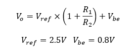
R1 and R2 were chosen for a designed output voltage of 5.0V.
When the input voltage falls below about 5.6V, the output voltage will simply be input voltage less voltage drop across B-E of the transistor.
At 5.59V input with 1.0A load we get 5.0V output.
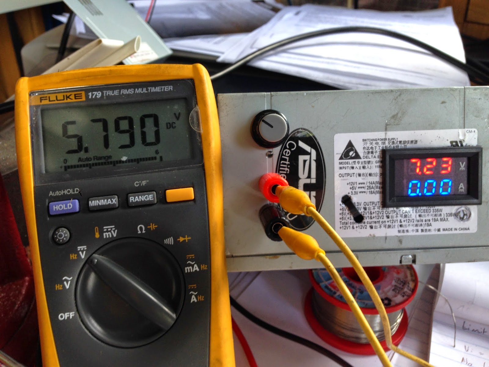
At 7.2V input, the circuit provides 5.79V. Looks like transistor B-E voltage drop is 0.79V at 1.0A load.
Although 10V won't be encountered in the R/C car I thought I'd see how the circuit handled this condition. Still good, output voltage within the designed range of 4.5V to 6.0V.
And here's the assembled circuit, using 'high rise architecture' method.
I put the whole thing in some large heatshrink before installing in the car.


No comments:
Post a Comment