Sunday, 31 December 2017

Don't buy from Pswpower!

Considering buying from Pswpower?  Read on for some sobering advice...

Recently I purchased an electric bike kit.  I wanted to try out the torque sense system in a Chinese mid-mounted motor setup.

I have all the bike tools I could possibly need and plenty of electronics knowledge.

One thing I have learnt about myself is that a love a great deal!  To that end I decided to go with a kit rather than a complete bike and to order direct from China using AliExpress.  I ordered the VLCD5 + TSDZ2 electric bike kit (no battery) from Pswpower and Samsung cell battery from another seller to get the best deal on each.

The battery took about 4 weeks to arrive.  The delay was in part due to 1 week for assembly (I guess they are made to order?) plus a mysterious 2 week delay after arriving in Australia (security measures for battery imports?).  The order from Pswpower arrived in an impressive 4 days!  However, my feelings about the 2 AliExpress vendors were soon to be reversed.

The electric bike kit remained in the box for 3 weeks while I waiting for the battery to arrive.  When the battery finally arrived I installed the kit. I found I had to fabricate a custom aluminium bracket to suit my bike frame, but for me this was all part of the fun!  Overall installation was easy.


First problem I encountered was speed display quickly shot up to 99.9km/h at walking pace.


My oscilloscope confirmed the speed sensor hall effect device was faulty.  Multiple pulses from the sensor during single pass of the magnet.


When I contacted Pswpower about the faulty sensor I was told I had to pay for a replacement sensor.

When I pushed for the item to be replaced under warranty I received this:

But I had more issues.  I frequently saw E04 error and the system stops working altogether. 


Confusing wording in initial response from Pswpower left me curious.

At least the next response was clearer.

And, the torque sensing system had problems too.  It worked ok on initial take off but after coming to a stop and attempting to take off again the torque sense no longer functions and I am left pedalling without any electric help!

I asked again for warranty replacement from Pswpower and I received:
Hmm...  maybe a template response?

That's where I am today.  AliExpress buyer protection has expired too so I am not able to open a dispute via the AleExpress website.  I am left with a completely unusable electric bike and a seller that won't honour their warranty.

My advice: Don't buy from Pswpower.


Sunday, 10 July 2016

BMW X5 E53 4.4i Alternator Rebuild

BMW X5 4.4i Alternator Rebuild

After successfully rebuilding the 180A Valeo alternator on a BMW E53 4.4i I thought I'd post a rebuild procedure.


Parts needed

  • Bearing o/d:47mm  i/d:17mm  thick:14mm
  • Bearing o/d:35mm  i/d:15mm  thick:11mm
  • Regulator (BMW 12318510090)

Tools

  • 1/2 inch drive, long T50 torx male
  • 24mm socket, modified to allow external spanner (see pics below)
  • ThreeBond 1207B sealant
  • Long 16mm socket (e.g. spark plug socket) for installing small bearing.
  • Bearing puller

Pre-work

Removing the fan cowl is essential.  Removing the radiator is not strictly necessary, but it makes the job of getting the alternator out much easier and avoids accidentally damaging the radiator.  I removed the radiator :-)

Procedure

There are 2 bearings a large and a small one.

The small bearing is pressed onto the rotor shaft using the 16mm spark plug socket.


There's not a lot of clearance below the small bearing, which necessitated the purchase of new bearing puller tool.  Cool!


The larger bearing presented a separate problem.  The rotor should slide into the large bearing - but it was stuck in the old bearing on this unit.  The retaining plate was completely destroyed when I pressed out the rotor from the case.


This was a perfect opportunity to have another play with Fusion 360.  Here's the replacement plate I decided to fabricate:

I have shared my Fusion 360 design and you are free to use it:  http://a360.co/29eWFaN
Please ping me (for karma) if you fabricate my design.


Here's the fabricated plate installed with the new bearing in place.


 Before re-assembly clean out the old black/grey sealant from both sides.


I used ThreeBond 1207B that I had in my toolbox (from the time I rebuilt the intake manifold system on this same car)

Apply the ThreeBond sealant to both halves.

Note the rubber seal (3mm x 1mm cross-section) just below the windings.

Excess sealant after screwing the casing back together.  I removed the excess with a rubber spatula then cleaned up with acetone.

Install new regulator assembly (no pics of this unfortunately).

This is the 24mm nut that retains the pully. 
A modified 24mm 1/2 inch socket is required so a spanner can be used while a long T50 torx stops the shaft from rotating.


Thanks for reading.

Wednesday, 30 March 2016

USB Cable Tester using Arduino UNO


Have you even wondered why your tablet or phone charges faster with one cable and slower with another?

I did, and questions like this keep me awake at night.  So, I designed a USB Cable Tester using an Android UNO board. 


This device measures the charge efficiency of a micro-USB cable by passing 0.5A through the cable and measuring voltage at various points.

To calculate the efficiency, we assume that the input current ITEST is identical to the output current that flows through the 10 ohm load resistor.  I.e. the internal resistance of the cable is negligible.


The efficiency is the ratio of input and output power, which simplifies down to the ratio of input and output voltage.

In order to get the most accurate result possible, this circuit measures both +ve and -ve sides of both Vout and Vin; and measurement points are taken as close as possible to the usb connectors.

The connections to the Arduino analog pins A0 - A3 are shown in the circuit diagram below.  Vcc is wired to 5V.


And here's the Arduino code.  Initially I found the value on the display 'flickered' as the Arduino was updating the display hundreds of times a second.  In this version of the code I have implemented oversampling in an attempt to provide a more 'stable' display of the efficiency value.


And finally, here's some pictures of the device in use.

A good cable (the best on I could find lying around) measured an efficiency of a little over 98%:

And here's an el-cheapo cable that measured a loss of nearly 10%  You know you wan't get optimal charge time with this one:

If you build this yourself please post a comment and let me know how it turned out.

Sunday, 9 November 2014

Simple R/C Battery Eliminator (Voltage Regulator) using parts salvaged from ATX Power Supply

In the course of building a Tamiya Blitzer Beetle with my son, we realised that the receiver unit couldn't be connected directly to the main 7.2V battery because the receiver has a required input voltage of 4.5V to 6.0V.  I didn't want to add a 4xAA battery pack, so we got to work desiging a voltage regulator. 

We took some current measurements of the receiver and found it could draw up to around 800mA.
 

Design parameters:
  • Input voltage:     7.2V
  • Output voltage:  4.5V to 6.0V
  • Output current:  1.0A
For an added challenge I thought I'd see if I could build this circuit using parts I had lying around.  

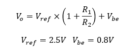
The key to this circuit is the TL431 Programmable Shunt Regulator.  TL431 are very common in ATX power supplies and are essentially an adjustable voltage reference.  Here's the TL431 block diagram:


Now, In order to supply the 800mA current we needed (TL431 is only rated to 100mA) we added an NPN power transistor (KSC5027, also salvaged from the same ATX psu).  Pretty much any NPN transistor will do provided it has sufficient current rating.

Here's the circuit:
  

'Power Controller' is the 7.2V connection.

R1 and R2 were chosen for a designed output voltage of 5.0V.  


When the input voltage falls below about 5.6V, the output voltage will simply be input voltage less voltage drop across B-E of the transistor.  

At 5.59V input with 1.0A load we get 5.0V output.


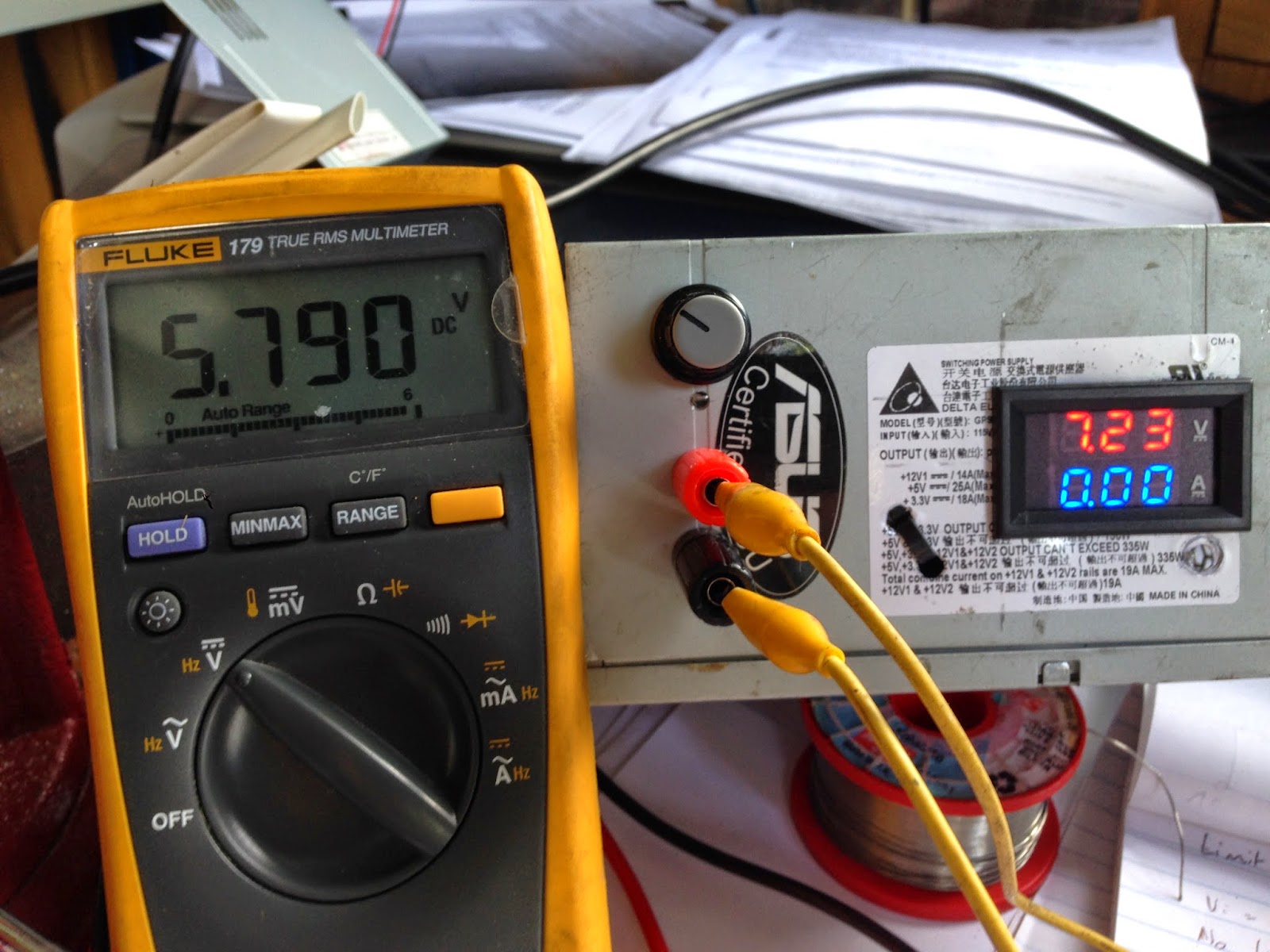
At 7.2V input, the circuit provides 5.79V.  Looks like transistor B-E voltage drop is 0.79V at 1.0A load.

Although 10V won't be encountered in the R/C car I thought I'd see how the circuit handled this condition.  Still good, output voltage within the designed range of 4.5V to 6.0V.

And here's the assembled circuit, using 'high rise architecture' method. 
I put the whole thing in some large heatshrink before installing in the car.
 

Thanks for reading.  Have fun with electronics!

Saturday, 22 February 2014

How to Disable Driver Signature Enforcement in Windows 8

Here's a quick post on how to disable the signature check for drivers in Windows 8 and allow unsigned drivers to be installed.

You might want to do this if a vendor's driver hasn't been signed, which I had to do for an old Tektronix Phaser 7700 printer; or if you are trying to load a modified driver, such as the HP 5590 ScanJet driver modified for 4500 ScanJet hardware, as described in another post at TheConstantMeddler.

If you attempt to In Windows 8 you are no longer prompted when attempting to install unsigned drivers, instead the driver installation fails silently or retries in an endless loop. Disabling driver signature enforcement requires restarting Windows 8, and then the ability to install unsigned drivers lasts until the next restart.

On to the procedure...

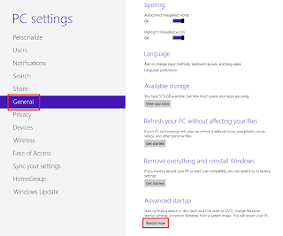
Show charms by moving cursor to screen top right, click Settings -> Change PC Settings -> General -> 'Restart Now' under Advanced Startup

Choose 'Troubleshoot'
Then 'Advanced Options'
'Startup Settings'
And click 'Restart' (we're almost there!)
Now press 7 to startup with Driver Signature Enforcement disabled.
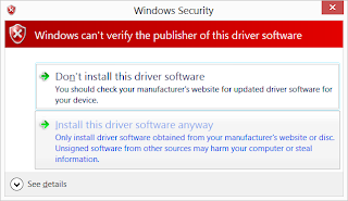
That's it. Now when you attempt to install an unsigned driver you should get a prompt like below allowing you to install.

Friday, 7 November 2008

Finally, a solution for HP ScanJet 4500C on Windows 7/8

2014-02-21 - Updated for Windows 8

I've been working at getting my old HP ScanJet 4500C working with Windows 7 x64 for a while now, and I finally cracked it!  I can't believe how simple the solution turned out to be.

So, straight into the details.

The basic idea is to use the HP driver software for the ScanJet 5590.  Since the 5590 has a different USB product id (1705) to the ScanJet 4500C (1205), we need to alter the 5590 software package's inf file before installing.

Uninstall any existing HP driver software for the ScanJet 4500C. In device manager uninstall the existing hp scanjet 4500 item.

1. Download the Full Feature Software and Driver package from the HP ScanJet 5590 drivers page.

2. Extract the contents of this file using your zip application. I recommend 7-zip.

3. Edit Hpgt5590.inf with a text editor and replace each occurrence of  '_1705' with '_1205' There should be 3.

4. Install the software by running HPZstub.exe. You might expect setup.exe to be the launcher, but it isn't. You can Connect your 4500c scanner when prompted during the install.

The remaining steps deal with driver signature enforcement in Windows 8
5. Since the .inf file has now been 'tampered' with, the supplied driver hash is invalid and Windows probably hasn't loaded the driver. To allow Windows to load our modified driver, go ahead and disable driver signature enforcement. If you don't know how to do this, check out this post.

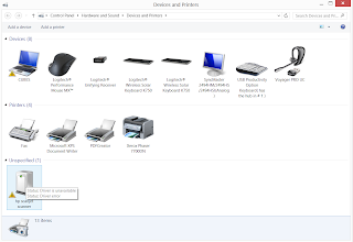
6. In Devices and Printers select the hp scanner device and update the driver.


Choose to specify driver from a specific location  and browse to the extracted 5590 files you created above. You will get a warning like this, go ahead and 'install the driver anyway'.


If HP Solution Center complains that it cannot find your scanner, it may be using the original 4500c/5550 driver. Go to device manager and uninstall the 4500c device. Re-install and specify the driver in the location of your modified Hpgt5590.inf file.

Happy scanning!